29 November 2010

25th/26th November 2010

Well, it has been a while since I set foot in the garage, owing to other commitments..so here goes. The main focus of work this week was to try disconnecting the electrics and take out as much stuff as I could that would hinder the removal of the bodywork.

Dad came up to help out with this and after a minor hold up with the phone engineers We set to with stripping out a few components that were running through the bodywork to the engine bay.
starting with the steering wheel, this needed to have one clamp removed from it on the other side of the bulkhead, (Engine side) the 5th picture down below shows some of the removal process.
We also took out the gauges and drew up a diagram for the resulting cable removal.
during the process we found that most of the switches have been damagedas the back sections that house the pins for cable connectors have come apart. These cannot be repaired and will need replacing when I hit an autojumble next. Mine in particular are Jaguar. Also removed were the various dials on the dashboard.
You can see tha switches that are damaged (most of them!) except for the third on up from the bottom and the one right at the top which still have pins attached to them. This photo should also be another way but the site seems to change it at will, and won't allow me to rotate!!
Loosening the drivers dash section in order to get the dials out. Another photo the site won't let me change!
I liked the retro appeal of this instrument, it has astalk on it for zero-ing the trip counter! this has an outlet in the lower dashboard for operation by the driver. You can see that this car has racked up an amazingly low mileage in its 40 year lifespan so far!
The leather cone shaped hole is for the stalk on the odometer to go through for the driver to operate. this one isnt pushed to zero like standard ones on a modern car, you turn the stalk to zero the counter.


The centre 'Boss' screw has already been removed from the steering wheel end, at this point detailed in a previous post. once this clamp has been removed, the steering wheel and connected rod will slide out leaving just the column itself  in place.

Steering Rack with larger shaft section removed with the wheel
Below is an illustration showing the shaft attached to the wheel:

Ok so moving from here the Dash now looks like this

Wheel removed, the retaining bolts shown against dashboard have been coated with WD40 to loosen up as these were quite badly rusted.


You can now stare down this centre steering column into the engine bay.
From here I moved on to disconnecting the column with all of its indicator and light lever controls. this took some time as even though I applied WD40 to the bolts holding it in place these were still very tight and there wasn't a lot of room to turn the spanners. It is necessary to loosen the rack before the main dashboard panel shown here is removed.
I was able to remove the dashboard panels and framework at this point, leaving the main bulkhead it all attaches to.
The upright pieces of wood are the mountings for the bulkhead this secures the dashboard in place. a series of small flat headed screws hold this item in place.
With dashboard now seperate from the rest of the car I was able to put them all together to give an impression of what this looks like in its completed form. I will use this as a template for the new veneer dash I will be having made specially to fit.

Rear of the dashboard panel
With this now removed It is now much more simple to get at the wiring and heater unit these items I am still to remove but at this point it was getting on in the day, getting colder, and I had some travelling to do the picture below shows the dash board with the fascia removed completely.

Fascia removed from the main ply dashboard carcass. wiring is still a bit chaotic here but is a lot easier to remove now
Next items on the list to remove are the Heater unit and pipes, the internal wiring loom also pictured above, the wiper motor and arm, and last but certainly not least, the Fuel tank (inclusive of fuel!) this will require a jack up of the car for me to get under and remove the retaining bolts. Thankfully dad has got me a shiny new set of axle stands and a trolley jack as an early Christmas present! : )

So Until Next weekend!


05 November 2010

Weekend 25-10-2010

Due to my internet being down I have had to post this some time later than I actually worked!
So, this weekend I got down to a few bits and pieces that i can do (without major assistance) and this started with an unscrewing of the Wiper motor assembly. as the photo below shows, this item is securely bolted to the bulkhead between engine and dashboard/cabin (and is a lot easier to accomplish with the windscreen removed as I have done)

There is a stainless steel retaining bracket that is placed around the cabin side of the unit. the two main bolts have been disconnected but the unit will stay seated in position due to the arm extending across to the drivers side still being held in place by other components (these I cannot remove until other items have been removed).

Retaining bolts for the Wiper motor unit (Engine side)
Wiper Motor, note: the bracket in place below the arm section (Glove compartment side)

Following this I began to tackle the boss and steering rack mountings, a very large wrench is needed here, together with a hammer to knock it loose. if the clamps are loosened along the length of the rack, the wheels will cease to turn when you hit it. (Handy)
 

Because at this point there were several items I wanted to check out, I finished up with this part and left for the next time in order to make sure I have the right things taken off!

Next in line I turned my attention to the body work, the bonnet has still got most of the fixings attached to it still and as I may decide to gently rub down the paint when I reach an impass on something else I decidd to remove some of the external trimming features. Most prominently the bumper mountings.

As the screws holding these in place are so badly rusted, it is almost inevitable that one will have to saw them off. I have used just a junior hacksaw as this is sufficient to get into the small gap and the blade is strong enough to take the strain. On the inside, a piece of 'hosing' not too dissimilar to a hozelock hose acts as a spacer between body and the inside of the fender strip.

The rear 'unseen' side of the fender strip
Looks rather different without those strips!
The Next Task I set to was with the removal of the Marcos Badge, thankfully as most ofthe car is complete, it still has one of the original badges (albeit in poor condition) This Badge can be re-enamelled to new again and is worth it as people are charging anything up to £100.00 for a new Badge!! The Plate will have to be removed soon too to allow for the rub down. The headlights as you can see have become temporary 'parts bins'.

Looking at this image and mentioned before, the surrounds within the light areas are heavily rusted and do break easily, I will need to look for parts from a Vauxhall Viva?? or similar? to replace.

Not sure what the lower indicator light units came from but the ones my dad used are Aston Martin but contain only a single bulb for indicator only this has spots in the same unit. I will probably re-use these to stick to original.

As I am working toward having the body off by Christmas, I removed a couple more metallic objects that will hinder the process these are the door lock units.


The boltsagain did move in their mountings so access to hold the retaining bolts in place had to come from the wheel arch behind.

Note: holding the rear side of the bolts in place while undoing the outside bolt.
Retaining bolts on the rear of the badge
That was about all I had time for this weekend, I am hoping to get back over the next week or so to start labelling up wires for disconnection.

G

05 October 2010

03/10/2010

After Yesterdays solid progress, I continued where I left off and decided to have a go at drilling out the rivets, (or very knackered screws as I later found them out to be) from the pedal Box cover. Fluids I think have caused these screws to be 'dissolved away' I used a bit of drilling together with some gentle persuasion from a hammer and a big handled screwdriver, managed to tap out the screw closest to the front bulkhead. the other stayed in its position but the box cover came away. it was necessary to unscrew the cable first from the back of the slave cylinder assembly as this cable runs through the side of the box and sort of keeps it there.

Drilling the first of the screws out.
What I found at this stage was that tapping out the screws from this area washindered by the location of the bonnet catch and the stay behind it, I removed these, and of course both were completely different! the passenger side one was more substantial and had loads of washers attached to it as opposed to driver side that only had 1.
Driver's side Bonnect catch
The camera had run out of juice by now and I had to resort to the phone so I hope the quality is ok!!!
The picture below shows the opposite side Bonnet clip and you can see the difference immediately to the drivers side one!

Washers between the outer part of the clip and the fibreglass (The Voltage regulator for the Dynamo marked 'Lucas' is fairly prominent too). I'm most likely going to use an alternator, so this part will be become redundant.
I movedback to the pedal box at this point and took out the plastic surround from around the cyclinders etc. once I had disconnected the cable running from the pedals out to the carburettor.

Pedal Box showing to the right, the Steering rack coming down with an additional clamping mechanism that must be removed to allow the rack to come away from the rest of the mechanism. (Note Dynamo bottom right)
Next up was the Radiator, oil cooler and fan dis-assembly, It was important to remove these parts so that the most amount of space could be gained to work (especially when removing engine and gearbox further down the line).

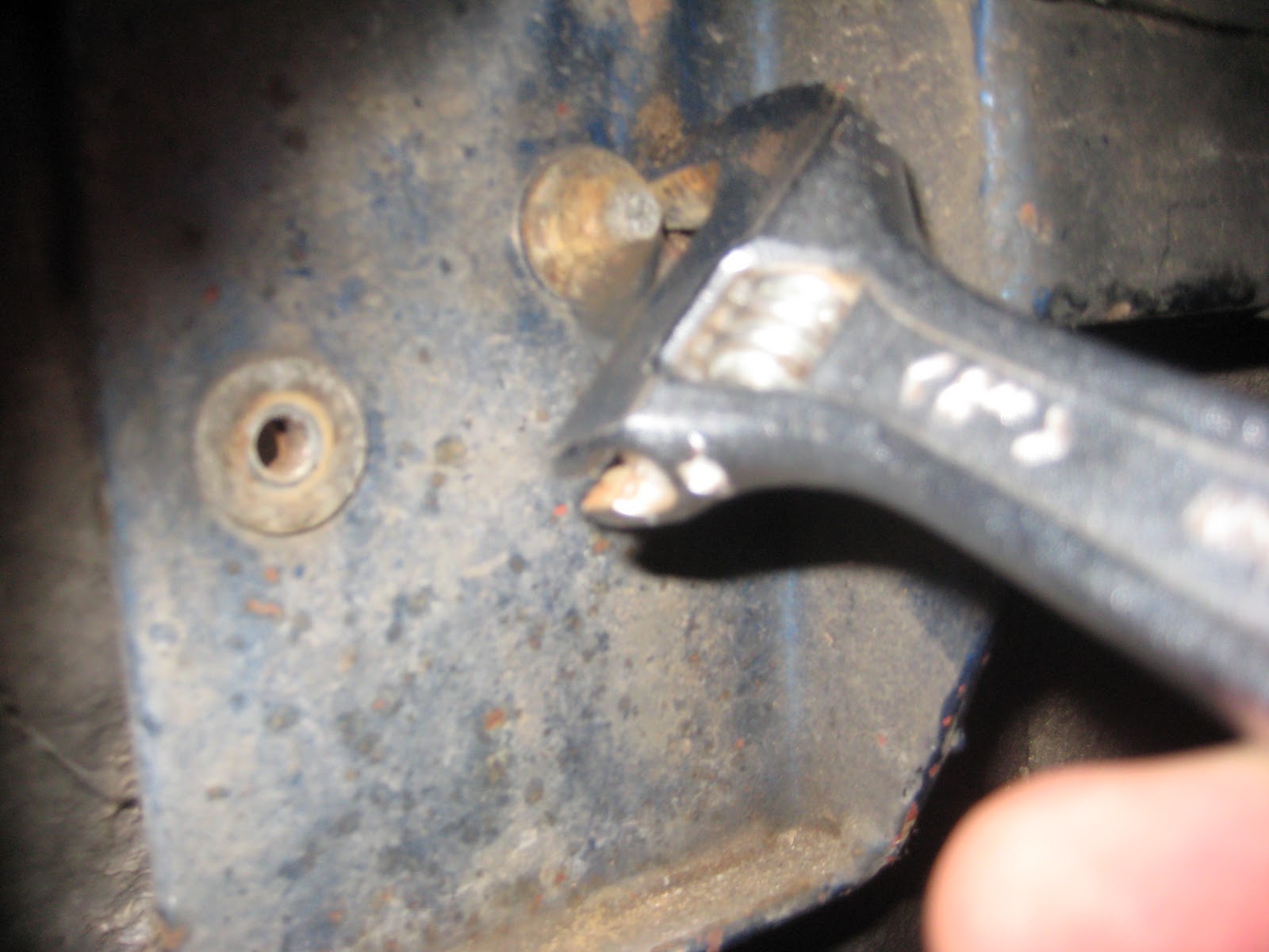
Looking at the rad there are four bolts, the bottom two were easy to remove, the top two there was only enough room to place a small adjustable spanner moving at one quarter turns each time, the rad had to be pulled forward to allow space for the bolt to work its way backwards sothat it could come off the screw thread.

Here I am removing the oil cooler, this wasnt really much of an obstacle, (even though the screws were rusty) just 4 secure this in total at the base of the unit.
Sowith the removal of the Fan, Radiator and water cooler from the front, the bay looks very sparse now!! there was a small leakage of water at this point (Orange water) this has obviously been in the pipe for some considerable time. and so it went everywhere!


Another view closer up of the front of the car One thing that has impressed me, is how the chassis looks in this incredibly 'exposed to the elements' area! I'm hoping the bits I can't see are at least as good as this. I know the rear sections in the wheel arch area are immaculate.
Another point I can bring up from Yesterdays workings, is the fact there are two flasher units in the car, my dad thinks there is a hazard warning system in place, that I don't think is put as standard on the V6's  or indeed earlier cars?
(See Picture Below).
The main flasher unit is at the very top of the dash fascia, the additional one is cylinder that is on the end of the wires in my hand.
Whilst pottering around the winscreen earlier it was clear that with the removal of the roof, this metal support has been put in place up to the top of the screen so this is a 'bonus' bit of strength for the screen which would otherwise be a major structuralpoint in just fibreglass! 
Anyway this was the end of this weekends work It will be a couple of weekend before I can update but should be able to acomplish much much more in the next set of weekends.

Bye for now!

Weekend 02/10/2010

Plenty to do in the shed so my dad popped up to help with a few things, the first thing was to remove the door, this I tried to do last time but had problems with the three remaining bolts in the top of the panel these have rusted solid, so I fear I may have to grind them off as wd40 and lots of turning didn't acheive success. We removed the door at the hinges and propped up the whole unit.
The next major thing I wanted to look at was the fuel tank it is one of the major elements that must must be removed in order to get the Body off, We were able to pull out the filler cap and disconnect the connecting pipe and hose, but as for taking the whole tank out, this needs access from underneath the car which at this time I can't do as I haven't yet purchased any axle stands so that I can get to the bolts underneath.


Here, the filler cap can be removed from the top and once the jubilee clips are loosened the hose can be removed through the hole in the bodywork. The resulting appearance is like so...
The rubber ring seals shown round the aperture here have degraded and will need to be replaced, it's best to keep the originals so that new alternatives can be found to match.

The next part we looked at was the Windscreen, now this was a lot easier than I had thought! as once the strips around the glass were removed, the window came out fairly freely. Again, important to keep the screen, even if you don't use it again, you have it as a blueprint as well as the sealing surround sand the silver strips that pull out of the groove between the glass and the seal.

Dad starts to remove the seals for the window and then lifts (after I've finished documenting it on camera!)

I remove the passenger side vertical strip


Screen now fully removed from the car.


A closer look at the edge of the window showing the roof was cut fairly cleanly from hereand would need a 2/3mm of filled fibreglass to make up the dpeth of the saw blade here if the roof is re-attached.

As we were in the area now of the steering column, I asked what was needed to remove the rack so that the remainder of the dash and instruments could be removed as well as the body being allowed to come off. the next few images show what must be taken off.

1st screw into the column needs to be removed, there is a bolt through the centre of the wheel that needs to be taken out also
There is a bolt on both of these stalks that have to be removed.
The two bolts on this clamp ned to be removed so that the clamp doesnt do its job of holding the column in place
More bolts here that have to be undone
Where there is a large concentration of blue wire, there is a gnurled nut in here that has to be removed carefully! as if this is lost, it will be a nightmare trying to find another! this holds the instrumentation in position and also allows disconnection of wires.
Once I was taken along the length of the column we disconnected the wipers and the stalks they are connected to, this will only come out once the wiper assembly is unbolted from the front bulkhead, these screws can be accessed (in the below piccy) through the dashboard, and the second picture from inside the engine bay.
Here the mounting bracket is clearly visible under the arm with bolts at either end
The two Main bolts for undoing the wiper motor are from the centre to the left of the image (to the left of the fuse box once these are undon the wiper motor also once disconnected from cables will come out.
Dad left me to my own devices at this point and I continued to work on a few other things around and about the car first of which was the glut of hoses that connect the radiator to the engine and the oil cooler to the engine. Here I am undoing the jubilee clips that fasten at each end of the pipe.

Image shows the very front mounted rad and the ends of the two hoses to the oil cooler the fan as it is setup at the moment, the plan is to get hold of a rad with a built in fan. mounted on the unit itself as opposed to a seperate system on a framework
Disconnection of water pipe to the radiator, jubilee clips on either end connect this up firmly, these have to be removed.
as you look at the front of the car, there is this device (Fuel pressure regulator), the horn controller, and currently a washer pump, I remove all these items at this stage.
Washer bottle bracket, this will need to be removed and then sited elsewhere once the new rad layout is in place
With light starting to fade a little, I stopped here and went indoors for Saturday. A lot of extraneous components have been removed at this point, the horn control unit, (Blue topped cylinder on the left) is still attached and so here are the horn trumpets behind the rad.